Two extruders, one purpose: what is X2D Direct Drive Extrusion and Auxiliary Extrusion?
Two heads as one sofisticated printing system
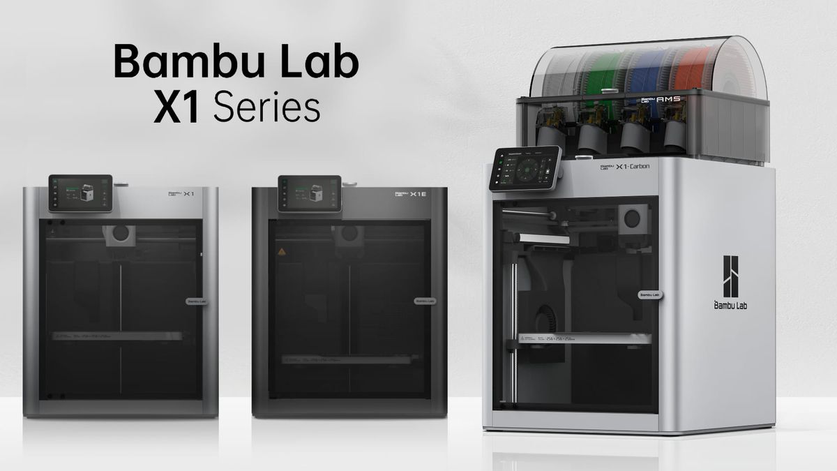
The X2D is a one-of-a-kind 3D printer that combines the best features of the iconic X1 Carbon, the newly released P2S, and the slightly older H2D. It has a compact design with a standard build volume of 256 × 256 × 260 mm. It is also packed with sensors monitoring its operation, making 3D printing an easy and smooth experience without unnecessary intervention.
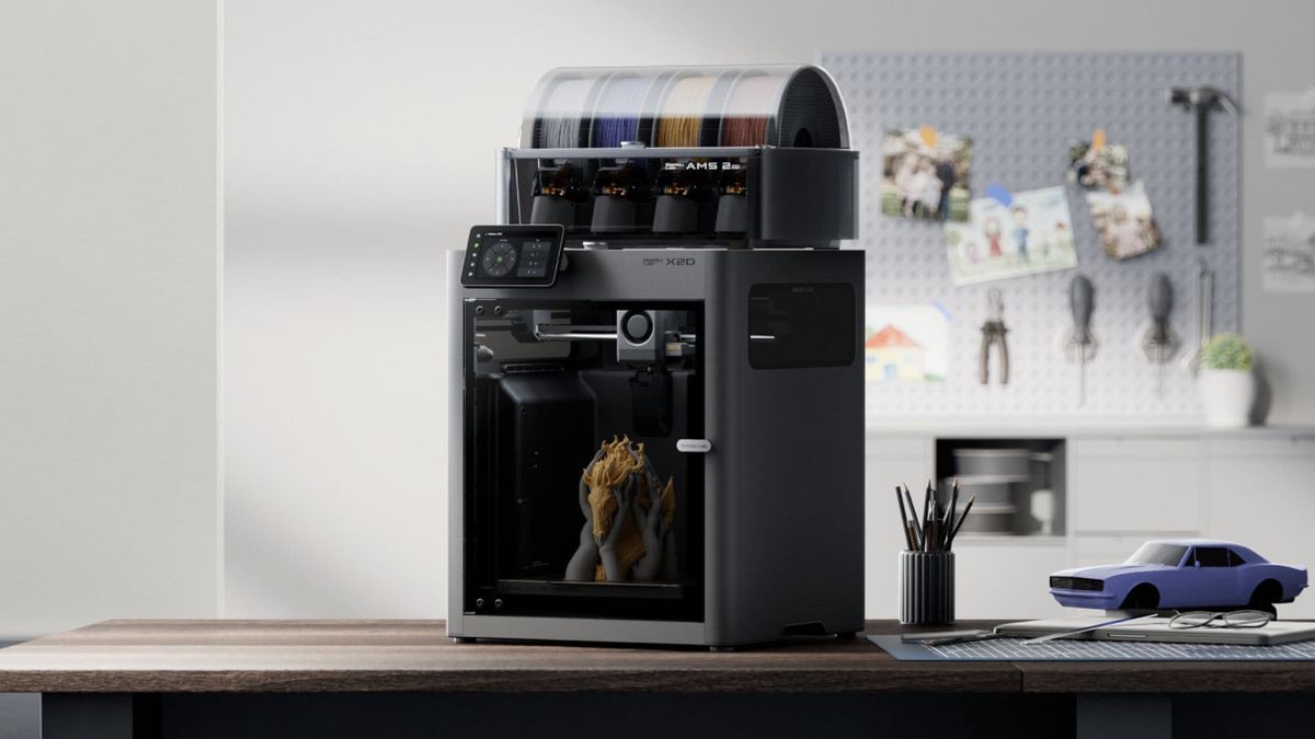
Its key feature - and the main difference compared to the X1 Carbon and P2S - is a system of two extruders and toolheads.
Typically, extruders are either placed side by side (direct extrusion) or mounted at the back of the printer (Bowden setup). In the X2D, this is solved differently - one could say in a hybrid way. Instead of a single universal solution, two distinct filament delivery systems were created, each designed to do exactly what it is best suited for.
Two philosophies of filament feeding
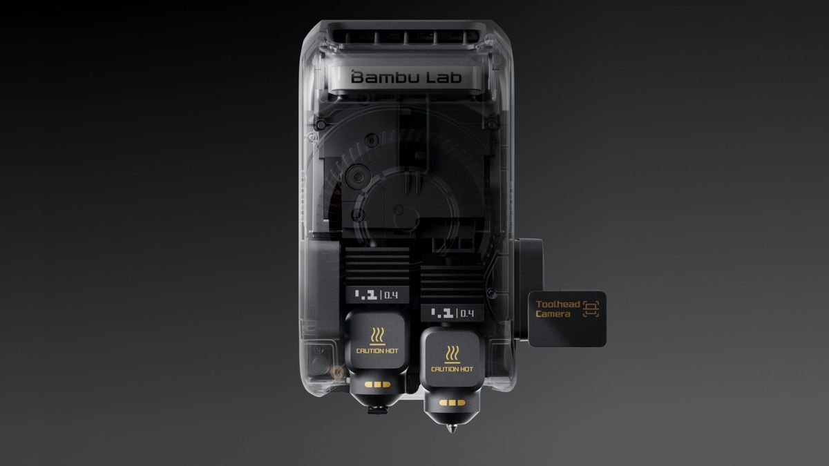
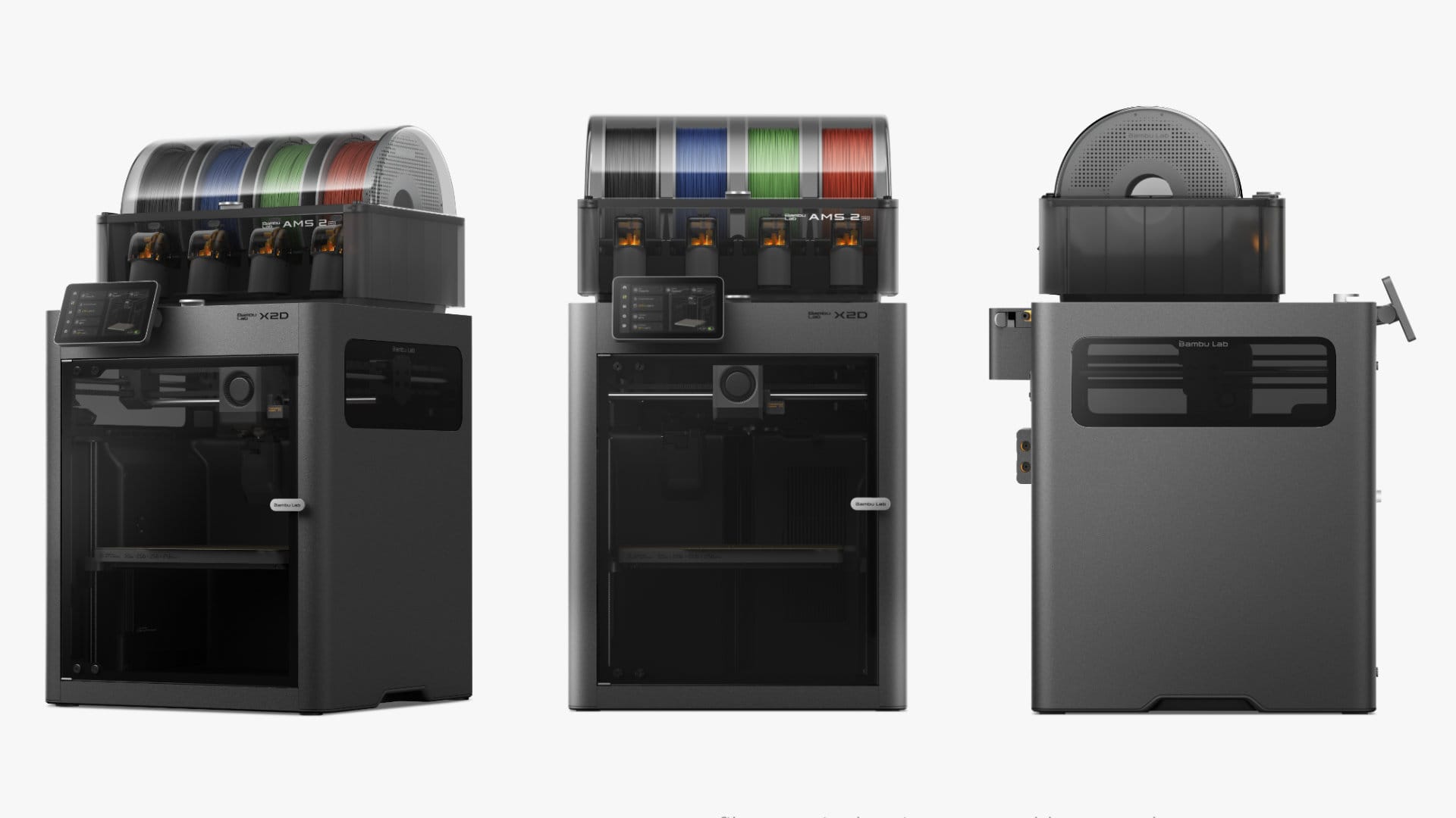
X2D is equipped with two extruders - the first (main) is installed directly on toolhead, while the second - auxiliary, is installed in the back of the printer. The main prints the model while the auxiliary prints the support.
The left head of the X2D is a classic direct drive system - the extruder is mounted directly in the toolhead, right next to the nozzle. The filament travels a very short path, almost immediately reaching the melting zone and being extruded with minimal delay. This setup ensures high precision, short retractions, and excellent flow control - ideal for primary materials where surface quality and geometric accuracy matter.
The right head is something entirely different: auxiliary extrusion. The extruder is not installed in the toolhead - it is mounted at the back of the printer, on the top panel. The filament travels a long distance through a PTFE tube before reaching the nozzle.
At first glance, this may look like a compromise. In reality, it is a deliberate design decision that brings specific advantages.
Why the Auxiliary Extruder is placed at the back - and what it means
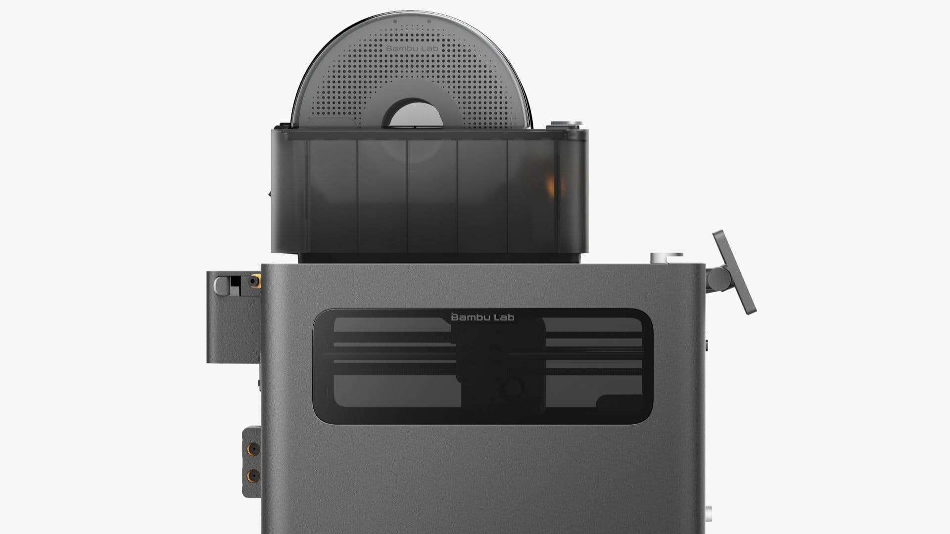
Moving the extruder outside the toolhead makes the print head lighter and smaller. Less moving mass means greater agility, fewer vibrations during direction changes, and better stability during dynamic movements. This allows the X2D to maintain high print quality despite having two active material delivery systems.
At the same time, this has a practical implication: placing two extruders side by side (as in H2D or H2C) would either significantly reduce the build volume or require enlarging the entire printer.
Instead, the goal was to maintain the standard established by the X and P series - the same build volumes and the same printer dimensions. This matters especially in 3D printing farms, where adding an X2D to an existing X1 or P1/P2 setup does not create integration issues.
The auxiliary extruder motor is a conventional stepper motor, but with increased pushing force. It needs this strength to overcome friction along the entire PTFE tube and deliver filament to the toolhead with stable pressure. And it does so effectively: despite the distance between the extruder and the nozzle, material feed stability remains high, and the risk of filament jams is significantly reduced.
It is also worth noting the mechanical details that show how refined this solution is. The locking nut securing the PTFE tube at the auxiliary extruder output is the same component as the one at the toolhead input - designed for high pressure forces and much more durable than standard pneumatic fittings. Above the filament outlet, there is a small washer with a simple but clever function: when the nut is properly tightened, it produces a subtle click. Without the washer, this signal does not occur. This is an example of engineering that simplifies rather than complicates.
The long filament path - and its consequences
Every solution has its limitations, and in the case of auxiliary extrusion, they stem directly from physics. Filament traveling a long distance through a PTFE tube behaves differently than in a short direct drive system. It has slight elasticity - under pressure it stretches a bit, and during retraction it does not immediately return to its original position. This creates a delay in response, known as elastic hysteresis.
Additionally, friction along the entire tube absorbs part of the motor’s force, and there is a delay in pressure response at the nozzle - when the motor changes speed or direction, the nozzle reacts with a slight lag. All these effects lead to one conclusion: calibration parameters for auxiliary extrusion must differ from those of direct drive.
The most important difference is retraction length. In direct drive, a few millimeters are enough to effectively pull back the filament and prevent oozing between moves. In auxiliary extrusion, retraction must be significantly longer - because before the pulling force reaches the nozzle, it must first tension and straighten the filament inside the tube. Only after that does actual retraction at the nozzle occur.
Similarly, the K parameter - the flow dynamics calibration coefficient - is much higher for auxiliary extrusion than for direct drive. This is not a flaw but a characteristic: a higher K means the firmware accounts for a greater delay between motor commands and the actual movement of filament at the nozzle. Without this correction, print quality would degrade during speed and direction changes.
Which head to use - and why it makes sense
The right head also has limitations related to motion dynamics. Because it must regularly move up and down during printing, and the long filament path requires more careful pressure management, the maximum print speed for auxiliary extrusion is 200 mm/s, and acceleration should not exceed 1000 mm/s². This is clearly lower than what direct drive offers - but in the context of the typical use of the right head, it is not a practical limitation.
We recommend treating the left head as the primary one - for structural material - and the right as auxiliary, for printing supports.
This makes sense not only from a technical standpoint. The right head can handle a wide range of support filaments. The left head, as a direct drive system, is better suited for materials requiring precision and high surface quality.It is also worth noting that activating the right head lowers the flow blocker below the left nozzle and moves the right hotend downward, reducing the maximum print height by 4 mm. This is not a major limitation, but it should be considered when planning a print.
Two heads as one system

The X2D is not a printer with two identical heads. It is a printer where two different filament delivery philosophies work together within a single, well-designed system. The left head does what direct drive does best: precision, dynamics, and control. The right head does what direct drive does not excel at: secondary materials, supports, a lighter toolhead, and stable long-distance feeding.
This distinction is not a compromise - it is a choice. Instead of trying to design a single extruder that does everything moderately well, two were built - each performing its specific role exceptionally well.
That is what makes the X2D more than just a dual-head printer.
And let’s be honest - it is another new standard we are setting, just as we did with the X1 series and all subsequent systems.
Additional technical specification
Recommended filaments:
Recommended: PLA (excluding PLA Aero), PETG, ABS, ASA, TPU for AMS, Support for PLA, Support for PLA/PETG, Support for ABS, Support for PA/PET, PET, PA, PC, PVA; PLA-CF/PLA-GF, PETG, ABS, ASA, PAG, PAHT, PET
Print with Caution: PLA Silk, PETG-CF, ASA-CF, PAG-CF, TPU for AMS, Support for PA/PET
Print area and range description:
When printing with the auxiliary hotend, the flow blocker moves below the left hotend and the right hotend lowers, resulting in a 4 mm reduction in print height. The specific print areas:
- X2D default print area = 256 x 256 x 260 mm
- Left nozzle = 256 x 256 x 260 mm
- Right nozzle = 235.5 x 256 x 256 mm
- Both nozzles = 235.5 x 256 x 256 mm
Go deeper: